CBHR - Continuous Blowdown Heat Recovery
Features
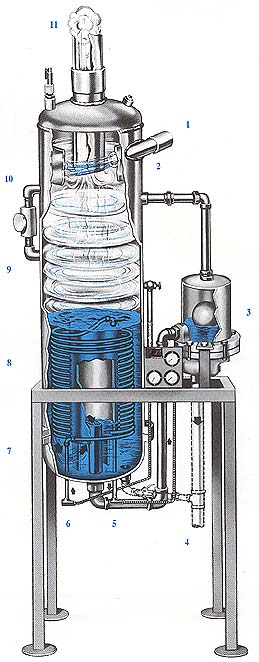
- Stainless Steel wear Plate at point of impingement prevents erosion of separator wall.
- Float Trap for continuous discharge of cooled water to drain.
- Cooled Blowdown to drain (100-110°).
- Boiler Make-Up exits heated by continuous blowdown at no extra cost.
- Cold Water boiler make-up enters system.
- Sludge Area no pockets or baffles in heat exchanger area for sludge to deposit and reduce heat recovery efficiency or to clop the flow area.
- Spiral Coil Heat Exchanger designed to provide maximum heat transfer.
- High Velocity Centrifugal Action drives liquid and solids to outside – only clean dry steam releases into central vortex area and up into steam outlet.
- Low Pressure Vortex Area expedites instant flashing of all steam to outlet.
- Steam Outlet clean dry steam 97% quality to deaerator.
Selection Chart
|
CBHR MODEL
|
BLOW DOWN
|
MAKE UP
|
A
|
B
|
C
|
D
|
E
|
F
|
G
|
H
|
I
|
J
|
K
|
L
|
M
|
|---|---|---|---|---|---|---|---|---|---|---|---|---|---|---|---|
|
CBHR3-15
|
3
|
15
|
97
|
46
|
40
|
10.75
|
1.5
|
2.5
|
1
|
1
|
37.25
|
17.75
|
28.00
|
8.50
|
9.0
|
|
CBHR6-30
|
6
|
30
|
111
|
53
|
46
|
12.75
|
1.5
|
3
|
1
|
1.25
|
35.00
|
19.00
|
27.00
|
11.00
|
9.0
|
|
CBHR10-50
|
10
|
50
|
106
|
51
|
43
|
16.00
|
1.5
|
4
|
2
|
1.5
|
41.50
|
23.50
|
32.25
|
14.25
|
9.0
|
|
CBHR20-100
|
20
|
100
|
140
|
68
|
60
|
18.00
|
1.5
|
6
|
2
|
2
|
45.00
|
25.00
|
35.75
|
15.75
|
9.0
|
|
CBHR30-150
|
30
|
150
|
132.5
|
67
|
51.25
|
24.00
|
1.5
|
6
|
2
|
2.5
|
51.00
|
33.00
|
41.75
|
23.75
|
9.0
|
Furnish and install as shown on drawings, a Kansas City Deaerator Continuous Blowdown w/Heat Recovery MODEL NO. (CBHR) ___________________ as manufactured by Kansas City Deaerator Company, Inc.
The Flash Economizer shall be capable of handling ________________ #/hr. continuous blowdown and ________________ gpm make-up at the boiler operating pressure/pressures of_____________ psig. flashing to low pressure deaerator, feedwater heater or other low pressure user at ______________ psig.
The Flash Economizer shall consist of the following components and accessories:
- Vertical Flash Separator section with threaded connections for tangential inlet with stainless steel wear plate, blowdown drain recovered steam vent, and tank cleanout connections as well as couplings as required for accessories.
- Vertical coil-type heat exchanger made of (copper or stainless steel) with steel threaded connections for make-up inlet, outlet, and openings for remote thermometer bulbs.
- Flanged bottom section with drop out coil design for easy cleaning and maintenance.
- Balanced float trap with all working parts constructed of stainless steel with removable seats, located externally and back vented to maintain a constant level in the flash separator.
- Thermometer gauge panel showing temperatures of the make-up inlet, make-up outlet, and blowdown water to drain.
- A safety relief valve set at 150 psig, a Michigan site level gauge, and tank clean out valve.
- Optional Accessories shall include a high level alarm switch, multi-boiler manifold, flow control or blowdown valves, pressure gauge, and sample cooler with piping.
All the above components shall be mounted on a table base with four angle iron floor supports and pads in such a manner that will allow gravity flow of blowdown water through the system. The finished system shall be painted with a blue enamel exterior.
The equipment shall be designed and constructed in accordance with the latest Code Sec. VIII, Div. 1. requirements for a unfired pressure vessel for 150 psig MAWP.