BFS - Boiler Feed Systems
Kansas City Deaerator’s Boiler Feed Systems can be used in applications when a deaerator is not feasible and/or desirable. In addition, the systems can be equipped with low pressure pumps and utilized as a condensate receiver.
Boiler Feed Systems should be sized to allow adequate storage volume for anticipated surges and to ensure sufficient reserves while plan controls react to changing.
Features
Receiver Selection
|
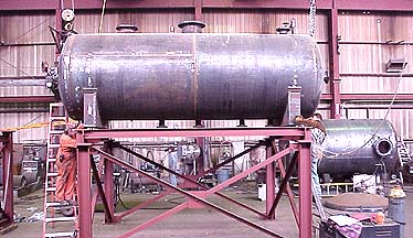
Receiver
Size (Gallons) |
A
|
B
|
C
|
D
|
E
|
F
|
G
|
H
|
J
|
K
|
L
|
M
|
|---|---|---|---|---|---|---|---|---|---|---|---|---|
|
21
|
14
|
30
|
30
|
42
|
45 ¼
|
30
|
27 ½
|
27 ½
|
1
|
2
|
36 ½
|
13 ¾
|
|
49
|
22
|
30
|
30
|
49 7/8
|
53 ¼
|
30
|
27 ½
|
27 ½
|
1 ¼
|
2 ½
|
36 ½
|
13 ¾
|
|
71
|
24
|
36
|
36
|
51 ½
|
55 ¼
|
32
|
29 ½
|
33 ½
|
1 ½
|
3
|
42 ½
|
14
|
|
117
|
24
|
60
|
36
|
51
|
55 ½
|
32
|
29 ½
|
33 ½
|
2
|
4
|
66 ½
|
14
|
|
209
|
32
|
60
|
50
|
58
|
63 ¾
|
50
|
47 ½
|
47 ½
|
2
|
5
|
66 ½
|
22
|
|
260
|
36
|
60
|
50
|
62
|
67 7/8
|
50
|
47 ½
|
47 ½
|
2
|
5
|
66 ½
|
22
|
|
370
|
36
|
84
|
50
|
62
|
68
|
50
|
47 ½
|
47 ½
|
2
|
5
|
90 ½
|
22
|
|
500
|
42
|
84
|
50
|
68
|
74
|
50
|
47 ½
|
47 ½
|
2
|
5
|
90 ½
|
22
|
|
650
|
42
|
108
|
50
|
68
|
74
|
50
|
47 ½
|
47 ½
|
2
|
5
|
114 ½
|
22
|
|
750
|
48
|
96
|
76
|
74
|
80
|
56
|
53 ½
|
73 ½
|
2
|
5
|
102 ½
|
25
|
|
1000
|
48
|
132
|
76
|
74
|
80
|
56
|
53 ½
|
73 ½
|
2
|
5
|
138 ½
|
25
|
|
Pump Capacity
|
GPM
|
1.5
|
3
|
6
|
9
|
12
|
15
|
22.5
|
30
|
37.5
|
45
|
60
|
75
|
97.5
|
150
|
187.5
|
|---|---|---|---|---|---|---|---|---|---|---|---|---|---|---|---|---|
|
PSI
|
EDR
|
1,000
|
2,000
|
4,000
|
6,000
|
8,000
|
10,000
|
15,000
|
20,000
|
25,000
|
30,000
|
40,000
|
50,000
|
65,000
|
100,000
|
125,000
|
|
10
|
Motor H.P
|
1/3
|
1/3
|
1/3
|
1/3
|
1/3
|
1/3
|
1/3
|
1/2
|
1/2
|
1/2
|
1
|
1 ½
|
2
|
1 ½
|
2
|
|
Suction
|
1 ¼
|
1 ¼
|
1 ¼
|
1 ¼
|
1 ¼
|
1 ¼
|
1 ¼
|
1 ¼
|
1 ¼
|
1 ¼
|
1 ½
|
1 ½
|
1 ½
|
2 ½
|
2 ½
|
|
|
Discharge
|
1
|
1
|
1
|
1
|
1
|
1
|
1
|
1
|
1
|
1
|
1 ¼
|
1 ¼
|
1 ¼
|
2
|
2
|
|
|
15
|
Motor H.P
|
1/3
|
1/3
|
1/3
|
1/3
|
1/3
|
1/3
|
1/3
|
1/2
|
1/2
|
1/2
|
1
|
1 ½
|
2
|
3
|
3
|
|
Suction
|
1 ¼
|
1 ¼
|
1 ¼
|
1 ¼
|
1 ¼
|
1 ¼
|
1 ¼
|
1 ¼
|
1 ¼
|
1 ¼
|
1 ½
|
1 ½
|
1 ½
|
2 ½
|
2 ½
|
|
|
Discharge
|
1
|
1
|
1
|
1
|
1
|
1
|
1
|
1
|
1
|
1
|
1 ¼
|
1 ¼
|
1 ¼
|
2
|
2
|
|
|
20
|
Motor H.P
|
1/3
|
1/3
|
1/3
|
1/3
|
1/3
|
1/2
|
1/2
|
3/4
|
3/4
|
1
|
1 ½
|
1 ½
|
2
|
3
|
5
|
|
Suction
|
1 ¼
|
1 ¼
|
1 ¼
|
1 ¼
|
1 ¼
|
1 ¼
|
1 ¼
|
1 ¼
|
1 ¼
|
1 ¼
|
1 ½
|
1 ½
|
1 ½
|
3
|
3
|
|
|
Discharge
|
1
|
1
|
1
|
1
|
1
|
1
|
1
|
1
|
1
|
1
|
1 ¼
|
1 ¼
|
1 ¼
|
2 ½
|
2 ½
|
|
|
30
|
Motor H.P
|
3/4
|
3/4
|
3/4
|
3/4
|
3/4
|
3/4
|
3/4
|
1
|
1
|
1 ½
|
2
|
2
|
5
|
2
|
7 ½
|
|
Suction
|
1 ¼
|
1 ¼
|
1 ¼
|
1 ¼
|
1 ¼
|
1 ¼
|
1 ¼
|
1 ¼
|
1 ¼
|
1 ½
|
1 ½
|
1 ½
|
2
|
2
|
2
|
|
|
Discharge
|
1
|
1
|
1
|
1
|
1
|
1
|
1
|
1
|
1
|
1 ¼
|
1 ¼
|
1 ¼
|
1 ½
|
1 ½
|
1 ½
|
|
|
40
|
Motor H.P
|
1
|
1
|
1
|
1
|
1
|
1
|
1
|
1 ½
|
1 ½
|
2
|
2
|
3
|
5
|
7 ½
|
7 ½
|
|
Suction
|
1 ¼
|
1 ¼
|
1 ¼
|
1 ¼
|
1 ¼
|
1 ¼
|
1 ¼
|
1 ½
|
1 ½
|
1 ½
|
2
|
2
|
2
|
2
|
2
|
|
|
Discharge
|
1
|
1
|
1
|
1
|
1
|
1
|
1
|
1 ¼
|
1 ¼
|
1 ¼
|
1 ½
|
1
|
1
|
1
|
1
|
|
|
50
|
Motor H.P
|
2
|
2
|
2
|
2
|
2
|
2
|
2
|
2
|
2
|
2
|
5
|
5
|
5
|
7 ½
|
10
|
|
Suction
|
1 ½
|
1 ½
|
1 ½
|
1 ½
|
1 ½
|
1 ½
|
1 ½
|
1 ½
|
2
|
2
|
2
|
2
|
2
|
2
|
2
|
|
|
Discharge
|
1 ¼
|
1 ¼
|
1 ¼
|
1 ¼
|
1 ¼
|
1 ¼
|
1 ¼
|
1 ¼
|
1 ½
|
1 ½
|
1
|
1
|
1
|
1
|
1
|
|
|
60
|
Motor H.P
|
3
|
3
|
3
|
3
|
3
|
3
|
3
|
5
|
5
|
5
|
5
|
5
|
7 ½
|
10
|
15
|
|
Suction
|
2
|
2
|
2
|
2
|
2
|
2
|
2
|
2
|
2
|
2
|
2
|
2
|
2
|
2
|
2
|
|
|
Discharge
|
1
|
1
|
1
|
1
|
1
|
1
|
1
|
1
|
1
|
1
|
1
|
1
|
1 ½
|
1
|
1
|
|
|
75
|
Motor H.P
|
5
|
5
|
5
|
5
|
5
|
5
|
3
|
5
|
5
|
7 ½
|
7 ½
|
7 ½
|
10
|
15
|
15
|
|
Suction
|
2
|
2
|
2
|
2
|
2
|
2
|
2
|
2
|
2
|
2
|
2
|
2
|
2
|
2
|
2
|
|
|
Discharge
|
1
|
1
|
1
|
1
|
1
|
1
|
1
|
1
|
1
|
1
|
1
|
1
|
1
|
1
|
1
|
|
Condensate Pumps – Standard Equipment
Single condensate return units are equipped with a 2-pole, heavy-duty float switch activated by a float. The entire switch mechanism including flange, float and rod is mounted on end of receiver, and it can be removed as a complete unit. The mechanism is readily adjustable for various water levels without removal from the receiver.
Duplex return units are equipped with a mechanical alternating float switch which alternates the operation of two pumping unit in successive cycles. It consists of two 2-pole switch units in one enclosure, and is operated by one float within the receiver. This device not only alternates the pumping units, but also automatically starts the second pump in case the first pump fails to start or to carry the loan.
Tappings for gauge glass and thermometer are standard on all H Series receiver tanks.
Condensate Pumps – Optional Equipment
Boiler Feed Pumps – Standard Equipment
Single and duplex boiler feed units are equipped with a heavy duty float operated makeup valve actuated by a float. The entire mechanism including flange, float and rod is mounted on the end of receiver. It can be removed as a complete unit and is readily adjustable for various water levels. Tappings for gauge glass and thermometer are standard on all H series receiver tanks.
Boiler Feed Pumps – Optional Equipment