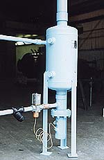
IB - Intermittant Blowdown with Aftercooler

Features
Download complete IB specifications PDF
Selection Chart
|
Blowdown Model
|
Boiler
Pressure (PSIG) |
Blow-down
(#/HR) |
Condensate
(GPM) |
Cold Water
(GPM) |
Tank Dia.
“A”(in) |
Tank Length
“B”(in) |
“C”
|
“D”
|
Inlet
“E” |
Drain
“F” |
Vent
“G” |
Cold
H20 “H” |
|---|---|---|---|---|---|---|---|---|---|---|---|---|
|
IB1420-1-2-2
|
50
|
6,444
|
12.17
|
12.52
|
14″
|
42″
|
2″
|
11″
|
1″
|
2″
|
2″
|
.5″
|
|
IB1420-1.25-3-3
|
50
|
13,472
|
25.44
|
26.17
|
14″
|
44″
|
4″
|
11″
|
1.25″
|
3″
|
3″
|
.5″
|
|
IB1434-1.5-3-3
|
50
|
19,437
|
36.70
|
37.76
|
14″
|
58″
|
4″
|
11″
|
1.25″
|
3″
|
3″
|
.75″
|
|
IB1434-2-4-4
|
50
|
37,454
|
70.69
|
72.74
|
14″
|
71″
|
11″
|
13″
|
2″
|
4″
|
4″
|
1.25″
|
|
IB1420-1-3-3
|
100
|
11,844
|
21.18
|
21.80
|
14″
|
44″
|
4″
|
11″
|
1″
|
3″
|
3″
|
.5″
|
|
IB1434-1.25-3-4
|
100
|
22,284
|
39.67
|
40.82
|
14″
|
60″
|
4″
|
13″
|
1.25″
|
3″
|
4″
|
.75″
|
|
IB1434-1.5-4-4
|
100
|
33,573
|
60.03
|
61.77
|
14″
|
71″
|
11″
|
13″
|
1.5″
|
4″
|
4″
|
1″
|
|
IB1434-2-4-6
|
100
|
60,356
|
108.24
|
111.38
|
14″
|
71″
|
11″
|
13″
|
2″
|
4″
|
6″
|
2″
|
|
IB1434-1-3-4
|
150
|
15,394
|
26.48
|
27.25
|
14″
|
60″
|
4″
|
13″
|
1″
|
3″
|
4″
|
.5″
|
|
IB1434-1.25-4-4
|
150
|
30,792
|
52.96
|
54.50
|
14″
|
71″
|
11″
|
13″
|
1.25″
|
4″
|
4″
|
1″
|
|
IB1434-1.5-4-6
|
150
|
44,625
|
76.88
|
79.11
|
14″
|
71″
|
11″
|
13″
|
1.50″
|
4″
|
6″
|
1.25″
|
|
IB1456-2-6-6
|
150
|
79,721
|
137.12
|
141.09
|
14″
|
96″
|
13″
|
13″
|
2″
|
6″
|
6″
|
2″
|
|
IB1434-1-3-4
|
200
|
19,690
|
32.84
|
33.80
|
14″
|
60″
|
4″
|
13″
|
1″
|
3″
|
4″
|
.75″
|
|
IB1434-1.25-4-6
|
200
|
37,848
|
63.13
|
64.96
|
14″
|
71″
|
11″
|
13″
|
1.25″
|
4″
|
6″
|
1.25″
|
|
IB1456-1.5-4-6
|
200
|
53,893
|
89.89
|
92.50
|
14″
|
93″
|
11″
|
13″
|
1.25″
|
4″
|
6″
|
1.5″
|
|
IB1456-2-6-6
|
200
|
94,496
|
157.62
|
162.19
|
14″
|
96″
|
13″
|
13″
|
2″
|
6″
|
6″
|
2″
|
|
IB1434-1-4-4
|
250
|
21,838
|
35.25
|
36.27
|
14″
|
71″
|
11″
|
13″
|
1″
|
4″
|
4″
|
1″
|
|
IB1456-1.25-4-6
|
250
|
42,339
|
68.34
|
70.32
|
14″
|
93″
|
11″
|
13″
|
1.25″
|
4″
|
6″
|
1.5″
|
|
IB1456-1.5-4-6
|
250
|
60,962
|
98.39
|
101.25
|
14″
|
93″
|
11″
|
13″
|
1.50″
|
4″
|
6″
|
2″
|
|
IB1456-2-6-8
|
250
|
109,261
|
176.35
|
181.46
|
14″
|
96″
|
13″
|
13″
|
2″
|
6″
|
8″
|
2.5″
|
|
IB1456-1-4-6
|
300
|
25,060
|
39.70
|
40.85
|
14″
|
93″
|
11″
|
13″
|
1″
|
4″
|
6″
|
1″
|
|
IB1456-1.25-4-6
|
300
|
48,754
|
77.23
|
79.47
|
14″
|
93″
|
11″
|
13″
|
1.25″
|
4″
|
6″
|
1.5″
|
|
IB1456-1.5-6-6
|
300
|
69,796
|
110.56
|
113.76
|
14″
|
96″
|
13″
|
13″
|
1.50″
|
6″
|
6″
|
2″
|
|
IB1456-2-6-8
|
300
|
122,550
|
194.12
|
199.75
|
14″
|
96″
|
13″
|
13″
|
2″
|
6″
|
8″
|
2.5″
|
|
*CUSTOM SIZES AVAILABLE |
||||||||||||
Specifications
Blowdown Separator
Furnish and install as shown on plans:
( ) Boiler Blow-Down Separator(s). Model _______ ” Height _______ ‘ Inlet _______ Drain _______ ” Vent ……..Select Plate Thickness 5/16″ or 3/8″ thk …….. ASME Code 250 psig @ 450 Deg. F …….. W/Screwed, Weld Bevel, or Flanged connections. Separator to have Stainless Steel Striking Plate at point of inlet impingement, as manufactured by Kansas City Deaerator Company.
Separator Accessories
Furnish and install a separator w/3 Angle Legs for Floor Mounting ( ) or Wall Brackets ( ).
AND
Furnish and install as shown on plans for Manual Cooling of Drain Water Temperature Separator Aftercooler Model A5D- _______ ‘ w/ _______ ‘ C.W. I. (cold water inlet)
OR
Furnish and install as shown on plans for Automatic Control of Drain Water Temperature Separator Aftercooler Model 18DF _______ “, 16DS _______ “, or 20 AO _______ ” w/ _______ ” C.W.I., a Temperature Regulator Valve, Strainer, and a 2″ Dial Bimetal Thermometer.

A16DS – Simplified Automatic Aftercooler
Similar to our 18DF aftercooler described above only without the middle flanges. This aftercooler accommodates the cold water line, sensing bulb, and thermometer. Sizing should match the drain line size. Cooling water selection from Chart “B: assures adequate cooling of condensate to drain.
Self Actuating Temperature Regulator Valve
Automatically controls the flow of cooling water to the aftercooler fittings by responding to the temperature change at the bulb. Each is factory set at 135 deg. F. with an adjustable range from 115-180 deg. F. the 6′ capillary allows installation of the valve in the cold water line while the bulb is remotely located in the aftercooler. The valve size should correspond to the recommended size on Chart “B”.


“Y” Type Strainer
Cast iron construction with a .033 inch stainless steel screen are recommended prior to temperature regulator valve or solenoid valve in the cold water line to protect these cold water valves.
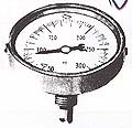
Bi-Metal Thermometer
Stainless steel body in 4″ or 6″ stainless steel stem. ¼” connection provided for use in the A18DF, A16DS or A20AO aftercoolers. Graduated scale shows temperature range 50 to 300 deg. F.

