Deaerator Accessories

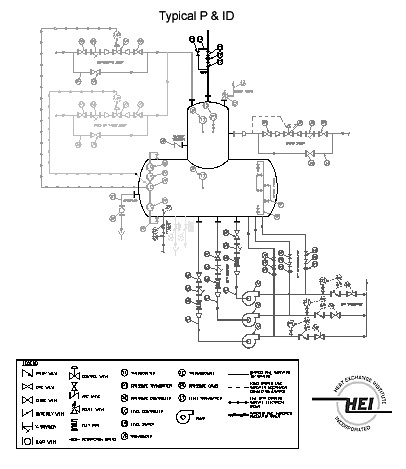
Kansas City Deaerator can provide accessories to complete the deaerator as a turnkey system. Typical systems include pressure and temperature monitoring, level control, pressure control, boiler feed pumps, boiler feed pump recirculation and control panels. Mechanical, pneumatic or electronic accessories can be utilized to interface with existing plant control systems.
Relief Valve

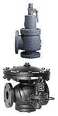
One or more relief valves are provided to either protect the pressure vessel against over-pressurization or act as sentinel relief. Overpressure can occur upon a failure of the steam pressure reducing valve, single or multiple trap discharges entering the deaerator or other conditions. It is the responsibility of the purchaser to evaluate all possible conditions and determine the worst case scenario for sizing the relief valve. If sentinel relief is selected by the customer for the deaerator, safety relief must be provided elsewhere in the system. When sentinel relief is selected, a nominally sized sentinel relief valve will be provided unless HEI is specified, in which case, sizing will be per HEI standards. The relief valve(s) are set to relieve at the deaerator design pressure.


A pressure gauge is provided for the steam space in the deaerator. A typical gauge would be 4 ½” dial (minimum) type with stainless steel bourdon tube construction. Either dry or liquid filled gauges may be specified. A siphon tube and shutoff cock for mounting the pressure gauge is included. In addition to considering the operating pressure of the deaerator, the gauge resolution (graduations) should be evaluated when selecting the pressure range of the pressure gauge.

Thermometers, when properly located, give a visual indication of deaerator performance. Preferred locations are the steam space of the deaerator, and under the water level in the storage area. Gauges are 5” dial (minimum) bimetal with stainless steel thermowells. Gauges should be constructed with adjustable viewing angle, hermetically sealed and with a stem length consistent with the location of the gauge in the deaerator. In addition to consideration of the operating temperature of the deaerator, the gauge resolution (graduations) should be evaluated when selecting the temperature range of the thermometer.

Control Valves are typically used to control the inlet water flow from one or more sources. The valve size depends on the required flow rate, temperature, and valve inlet and outlet pressures. The valve shall be modulating type with stainless steel trim and can be specified as mechanical, pneumatic or electronic. An external float cage and lever actuator are provided for a mechanically operated valve. For pneumatic control, a pneumatic actuator and caged displacer level controller are provided. If electronic control is specified, provide an I/P positioner on the valve to accepting a 4-20 ma input and a level transmitter are specified required.


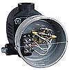
Level switches are utilized for warning of high or low water levels , actuating a pneumatic overflow valve, and/or for boiler feedpump cutoff. Audible or visible alarms may be specified if desired. As a minimum the switches shall have the following characteristics:
- Housings will be general purpose NEMA-1
- Switch ratings shall be 10 amps 120 VAC/DC
- Switch action shall be SPST
- Other housings, ratings, and actions may be specified
- Mercury or non-mercury switches may be specified

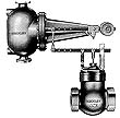
Overflow control valves are used to protect against high water level in the storage area. This device can be a float trap or a control valve with control sized to relieve the full capacity of deaerator.

Gauge glasses are used to visually indicate the liquid level in the storage tank . The glass consists of a water column with shutoff valves to cover 10%-90% of the water level in the storage section. Glass can be specified as tubular red line pyrex, reflex or magnetic type. The gauge glass should be rated for the operating temperature and pressure of the deaerator.


![]()
In addition to those shown here, Kansas City Deaerator can provide a wide variety of transmitters, controllers and other items. Consult with the factory for specialized applications.

|
ITEM
|
DESCRIPTION
|
ACC PKG
|
PUMP PKG
|
√
Select |
|---|---|---|---|---|
|
A
|
WATER INLET | |||
|
A1
|
Inlet Valve | |||
| Mechanical |
STD
|
STD
|
||
| Pneumatic |
OPT
|
OPT
|
||
|
A2
|
Level Controller |
STD
|
STD
|
|
| Level Transmitter |
OPT
|
OPT
|
||
|
A3
|
Inlet Valve Bypass Valves |
OPT
|
STD
|
|
|
A4
|
Inlet Valve Bypass Piping |
OPT
|
STD
|
|
|
A5
|
Inlet Valve Bypass Strainer |
OPT
|
STD
|
|
|
B
|
STEAM CONTROL | |||
|
B1
|
Steam PRV |
OPT
|
||
| Self Contained |
OPT
|
OPT
|
||
| Pneumatic |
OPT
|
OPT
|
||
|
B2
|
Steam PRV Controller |
OPT
|
OPT
|
|
|
B3
|
Steam PRV Bypass Valves |
OPT
|
OPT
|
|
|
B4
|
Steam PRV Bypass Piping |
OPT
|
OPT
|
|
|
B5
|
Steam PRV Bypass Strainer |
OPT
|
OPT
|
|
|
C
|
RELIEF VALVE | |||
|
C1
|
Relief Valve | |||
| Sentinel |
STD
|
STD
|
||
| Full |
OPT
|
OPT
|
||
|
C2
|
Relief Valve Exhaust Piping |
OPT
|
OPT
|
|
|
D
|
THERMOMETER | |||
|
D1
|
(2) 5″ Thermometer w/ss wells |
STD
|
STD
|
|
|
E
|
PRESSURE GAUGE | |||
|
E1
|
(1) 4 1/2″ Pressure Gauge |
STD
|
STD
|
|
|
E2
|
Siphon & Cock |
STD
|
STD
|
|
|
E3
|
Pressure Transmitter |
OPT
|
OPT
|
|
|
F
|
VENT | |||
|
F1
|
Vent Valve |
STD
|
STD
|
|
|
F2
|
Vent Orifice w/ Flange |
OPT
|
OPT
|
|
|
F3
|
Vent Bypass Valves |
OPT
|
OPT
|
|
|
F4
|
Vent Bypass Piping |
OPT
|
OPT
|
|
|
H
|
VACUUM BREAKER | |||
|
H1
|
Vacuum Breaker |
STD
|
STD
|
|
ITEM
|
DESCRIPTION
|
ACC PKG
|
PUMP PKG
|
√
Select |
|---|---|---|---|---|
|
M
|
BFP RECIRC | |||
|
M1
|
BFP Recirc Shutoff |
N/A
|
OPT
|
|
|
M2
|
BFP Recirc Check |
N/A
|
OPT
|
|
|
M3
|
BFP Recirc Orifice |
N/A
|
OPT
|
|
| BFP Recirc ARC Valve |
N/A
|
OPT
|
||
|
M4
|
BFP Recirc Piping |
N/A
|
OPT
|
|
|
M5
|
BFP Recirc Pressure Gauge |
N/A
|
OPT
|
|
|
N
|
BFP SUCTION | |||
|
N1
|
BF Pumps | |||
| (2) 100% Capacity |
N/A
|
STD
|
||
| (3) 50% Capacity |
N/A
|
OPT
|
||
| Motors | ||||
| ODP |
N/A
|
STD
|
||
| TEFC |
N/A
|
OPT
|
||
|
N2
|
BFP Suction Isolation Valve
|
N/A
|
STD
|
|
|
N3
|
BFP Suction Strainer
|
N/A
|
STD
|
|
|
N4
|
BFP Suction Piping
|
N/A
|
STD
|
|
|
N5
|
BFP Suction Expansion Joint
|
N/A
|
STD
|
|
|
N6
|
BFP Discharge Pressure Gauge
|
N/A
|
OPT
|
|
|
N7
|
BFP Discharge Check Valve
|
N/A
|
OPT
|
|
|
N8
|
BFP Discharge Isolation Valve
|
N/A
|
OPT
|
|
|
O
|
CHEMICAL FEED
|
|||
|
O
|
Chemical Feed Quill
|
OPT
|
OPT
|
|
|
Q
|
OVERFLOW
|
|||
|
Q1
|
Overflow Valve/Trap
|
STD
|
STD
|
|
|
Q3
|
Overflow Piping
|
OPT
|
STD
|
|
|
R
|
LEVEL SWITCHES
|
|||
|
R1
|
Level Switches
|
|||
| High and Low (TWO) |
STD
|
STD
|
||
| High High (ADDITIONAL) |
OPT
|
OPT
|
||
|
R2
|
Level Switch Bridle Piping
|
OPT
|
OPT
|
|
|
S
|
GAUGE GLASS
|
|||
|
S1
|
Gauge Glass
|
|||
| Red Line Pyrex |
STD
|
STD
|
||
| Reflex |
OPT
|
OPT
|
||
| Magnetic |
OPT
|
OPT
|
||
|
S2
|
Gauge Glass Bridle
|
OPT
|
STD
|
