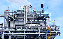
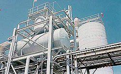
Custom Tray Deaerator


Corrosion in boiler cycles is caused by the presence of non-condensable gases such as oxygen and carbon dioxide in the boiler feed water. In order to remove the non-condensable gases, the feedwater is heated and vigorously scrubbed by a counter current flow of steam.
The incoming undeaerated water enters the deaerator though spring-loaded, stainless steel spray valves. These variable orifice valves produce a fine spray in a uniform pattern from 5% to 200% of design. The fine droplets of water maximize the surface area in contact with steam, raising the temperature to within a few degrees of saturation temperature and instantly releasing the majority of the corrosive, non-condensable gases.
The preheated and partially deaerated water flows through the tray stack where the hottest, purest steam vigorously scrubs the water to heat it to saturation temperature and strips the last traces of dissolved gases. Kansas City Deaerator Company trays are among the heaviest in the industry, fabricated of 16 gauge, type 430 stainless steel.
The entire deaeration process takes place in a stainless steel enclosure that eliminates any need for vessel lining or cladding and ensures a long life with little maintenance.
|
PROJECT |
|||||||
|
NO. UNITS |
|||||||
|
ARRANGEMENT |
|||||||
|
SPACE LIMITATIONS |
|||||||
|
PERFORMANCE REQUIREMENTS |
||||||||||
|---|---|---|---|---|---|---|---|---|---|---|
|
FLOW |
TEMP |
ENTHALPY |
PRESSURE |
|||||||
|
DESIGN |
#/HR |
DEG. F |
BTU/LB |
PSIG |
||||||
|
DELIVERED CAPACITY |
||||||||||
|
WATER INLET |
||||||||||
|
MAKEUP |
||||||||||
|
LP CONDENSATE |
||||||||||
|
HP CONDENSATE |
||||||||||
|
STEAM |
||||||||||
|
VENT RATE |
0.5 |
|||||||||
|
EFFLUENT O2 (cc/l) |
0.005 |
|||||||||
|
EFFLUENT CO2 (ppb) |
0 |
|||||||||
|
Storage Tank Cap. @ OF (gal) |
||||||||||
|
TECHNICAL REQUIREMENTS |
||||||||||
|---|---|---|---|---|---|---|---|---|---|---|
|
DESIGN |
CONNECTIONS |
SIZE |
RATING |
|||||||
|
ASME CODE LATEST EDITION |
SECTION VIII, DIV. 1 |
FEEDWATER |
||||||||
|
HEI LATEST EDITION |
REQ’D |
STEAM INLET |
||||||||
|
DESIGN PRESSURE (psig) |
RELIEF VALVE |
|||||||||
|
VACUUM |
THERMOMETER |
|||||||||
|
DESIGN TEMPERATURE (F) |
PRESSURE |
|||||||||
|
SHELL THICKNESS |
VENT |
|||||||||
|
HEAD THICKNESS |
HEATER MANWAY |
|||||||||
|
TYPE HEADS (F&D/2:1) |
HP RETURNS |
|||||||||
|
CORROSION ALLOWANCE |
0.025 INCH |
BFP RECIRC |
||||||||
|
VACUUM RINGS |
BFP SUCTION |
|||||||||
|
RADIOGRAPHY: HEAD & SHELL |
RT-2 MINIMUM |
OXYGEN SAMPLE |
||||||||
|
MAG. PARTICLE INSPECTION |
INTERNAL |
STORAGE |
||||||||
|
LIQUID DYE PENETRANT |
SS NOZZLES |
OVERFLOW |
||||||||
|
POST WELD HEAT TREATMENT |
REQ’D |
LEVEL CONTROL |
||||||||
|
CONNECTIONS |
GAUGE GLASS |
|||||||||
|
CHEMICAL FEED |
||||||||||
|
>2 INCH |
DRAIN |
|||||||||
|
MATERIALS OF CONSTRUCTION |
||||||||||
|---|---|---|---|---|---|---|---|---|---|---|
|
SHELL |
SA516-70 |
SUPPORTS |
SA-516-70 |
|||||||
|
HEADER |
SCH 10, 304L S.S. min |
BAFFLES |
304L SS |
|||||||
|
TRAYS |
16 ga, 430 S.S. |
NOZZLES |
A 106 gr. B |
|||||||
|
SPRAY VALVES |
316 S.S. |
FLANGES |
SA 105 |
|||||||
|
TRAY ENCLOSURE |
1/8″ 304L S.S. MIN |
|||||||||
|
VENT CONDENSER |
1/8″ 304L S.S. MIN |
|||||||||
|
ACCESSORIES |
||||||||||
|---|---|---|---|---|---|---|---|---|---|---|
|
FLOW (LBS/HR) |
PRESSURE (psig) |
|||||||||
|
Inlet Valve (specify one) |
Thermometer (2) |
|||||||||
|
Mechanical Control |
Pressure Gauge |
|||||||||
|
Pneumatic Control |
Vent Valve/Orifice |
|||||||||
|
Electronic Control |
||||||||||
|
Steam PRV (specify one) |
Overflow Valve |
|||||||||
|
Pneumatic Control |
Level Switch (2) |
|||||||||
|
Electronic Control |
Gauge Glass (specify one) |
|||||||||
|
Relief Valve |
– Red Line Pyrex |
|||||||||
|
Sentinel |
– Reflex |
|||||||||
|
Specified capacity |
– Magnetic |
|||||||||
|
NOTE: Marked items are |
||||||||||
Accessories
|
ITEM
|
DESCRIPTION
|
ACC PKG
|
PUMP PKG
|
√
Select |
|---|---|---|---|---|
|
A
|
WATER INLET | |||
|
A1
|
Inlet Valve | |||
| Mechanical |
STD
|
STD
|
||
| Pneumatic |
OPT
|
OPT
|
||
|
A2
|
Level Controller |
STD
|
STD
|
|
| Level Transmitter |
OPT
|
OPT
|
||
|
A3
|
Inlet Valve Bypass Valves |
OPT
|
STD
|
|
|
A4
|
Inlet Valve Bypass Piping |
OPT
|
STD
|
|
|
A5
|
Inlet Valve Bypass Strainer |
OPT
|
STD
|
|
|
B
|
STEAM CONTROL | |||
|
B1
|
Steam PRV |
OPT
|
||
| Self Contained |
OPT
|
OPT
|
||
| Pneumatic |
OPT
|
OPT
|
||
|
B2
|
Steam PRV Controller |
OPT
|
OPT
|
|
|
B3
|
Steam PRV Bypass Valves |
OPT
|
OPT
|
|
|
B4
|
Steam PRV Bypass Piping |
OPT
|
OPT
|
|
|
B5
|
Steam PRV Bypass Strainer |
OPT
|
OPT
|
|
|
C
|
RELIEF VALVE | |||
|
C1
|
Relief Valve | |||
| Sentinel |
STD
|
STD
|
||
| Full |
OPT
|
OPT
|
||
|
C2
|
Relief Valve Exhaust Piping |
OPT
|
OPT
|
|
|
D
|
THERMOMETER | |||
|
D1
|
(2) 5″ Thermometer w/ss wells |
STD
|
STD
|
|
|
E
|
PRESSURE GAUGE | |||
|
E1
|
(1) 4 1/2″ Pressure Gauge |
STD
|
STD
|
|
|
E2
|
Siphon & Cock |
STD
|
STD
|
|
|
E3
|
Pressure Transmitter |
OPT
|
OPT
|
|
|
F
|
VENT | |||
|
F1
|
Vent Valve |
STD
|
STD
|
|
|
F2
|
Vent Orifice w/ Flange |
OPT
|
OPT
|
|
|
F3
|
Vent Bypass Valves |
OPT
|
OPT
|
|
|
F4
|
Vent Bypass Piping |
OPT
|
OPT
|
|
|
H
|
VACUUM BREAKER | |||
|
H1
|
Vacuum Breaker |
STD
|
STD
|
|
ITEM
|
DESCRIPTION
|
ACC PKG
|
PUMP PKG
|
√
Select |
|---|---|---|---|---|
|
M
|
BFP RECIRC | |||
|
M1
|
BFP Recirc Shutoff |
N/A
|
OPT
|
|
|
M2
|
BFP Recirc Check |
N/A
|
OPT
|
|
|
M3
|
BFP Recirc Orifice |
N/A
|
OPT
|
|
| BFP Recirc ARC Valve |
N/A
|
OPT
|
||
|
M4
|
BFP Recirc Piping |
N/A
|
OPT
|
|
|
M5
|
BFP Recirc Pressure Gauge |
N/A
|
OPT
|
|
|
N
|
BFP SUCTION | |||
|
N1
|
BF Pumps | |||
| (2) 100% Capacity |
N/A
|
STD
|
||
| (3) 50% Capacity |
N/A
|
OPT
|
||
| Motors | ||||
| ODP |
N/A
|
STD
|
||
| TEFC |
N/A
|
OPT
|
||
|
N2
|
BFP Suction Isolation Valve
|
N/A
|
STD
|
|
|
N3
|
BFP Suction Strainer
|
N/A
|
STD
|
|
|
N4
|
BFP Suction Piping
|
N/A
|
STD
|
|
|
N5
|
BFP Suction Expansion Joint
|
N/A
|
STD
|
|
|
N6
|
BFP Discharge Pressure Gauge
|
N/A
|
OPT
|
|
|
N7
|
BFP Discharge Check Valve
|
N/A
|
OPT
|
|
|
N8
|
BFP Discharge Isolation Valve
|
N/A
|
OPT
|
|
|
O
|
CHEMICAL FEED
|
|||
|
O
|
Chemical Feed Quill
|
OPT
|
OPT
|
|
|
Q
|
OVERFLOW
|
|||
|
Q1
|
Overflow Valve/Trap
|
STD
|
STD
|
|
|
Q3
|
Overflow Piping
|
OPT
|
STD
|
|
|
R
|
LEVEL SWITCHES
|
|||
|
R1
|
Level Switches
|
|||
| High and Low (TWO) |
STD
|
STD
|
||
| High High (ADDITIONAL) |
OPT
|
OPT
|
||
|
R2
|
Level Switch Bridle Piping
|
OPT
|
OPT
|
|
|
S
|
GAUGE GLASS
|
|||
|
S1
|
Gauge Glass
|
|||
| Red Line Pyrex |
STD
|
STD
|
||
| Reflex |
OPT
|
OPT
|
||
| Magnetic |
OPT
|
OPT
|
||
|
S2
|
Gauge Glass Bridle
|
OPT
|
STD
|
